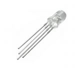
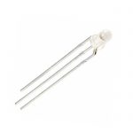
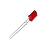
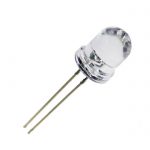
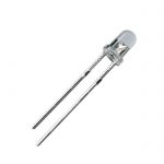
The dot matrix display is composed of tens of thousands of-hundreds of thousands of semiconductor light-emitting diode pixel points uniformly arranged. The dot matrix display uses different materials to produce different colors of LED pixel points. The dot matrix display is a way to control the display of semiconductor light-emitting diodes, LED Dot Matrix Display the dot matrix display is used to display text, graphics, images, animation, quotes, video, video signals and other information display screen.
Dot matrix display features are as follows:
Dot-matrix display can achieve ultra-high density: indoor up to 62.5 points/square meters (P4).
Dot matrix display Color good: the use of the light-emitting device itself micro-processing and light wave-particle duality, so that red particles, pure green particles, LED Dot Matrix Display blue light particles three kinds of particles will be fully mixed together.
Dot-matrix display antistatic Performance Advantage Super: The production environment has strict standards and product structure insulation design.
Lattice display reliability can be strong: relative to SMD and Ledlamp, LED Dot Matrix Display Leddot-matrix smoothness is very good, very aesthetic perception.
Dot-matrix display visual angle is large: 140 degrees (horizontal direction)
Dot-matrix display high permeability: The new generation of lattice technology by virtue of its own high purity of the performance of the chip, as well as nearly 100% optical transmittance of epoxy materials, LED Dot Matrix Display reached a close to the perfect permeability rate.
Dot-matrix display brightness: relative 0603 or 0805 in the form of discrete table stickers, led can have more luminous flux is reflected.
The principle of the dot matrix display driving circuit is as follows:
The driving circuit of dot matrix display is mainly composed of main chip control circuit, power supply circuit, control signal amplifying circuit and so on.
1. Main chip control circuit
Lattice display this part of the circuit is mainly composed of $literal and 74ls154. LED Dot Matrix Display MCU P0 and P2 number control display signal output, P1 number of low 4-bit control 74ls154 decoding input, thereby controlling the output of the scan signal.
2. Power supply Circuit
Dot matrix display the entire circuit power supply by the USB power supply, using our Computer host USB interface can output v voltage, LED Dot Matrix Display convenient for our laboratory debugging
3. Control signal amplifying circuit
To provide load capacity, the dot matrix display is amplified by 16 common 9013 NPN transistors in P0 and P2 ports. The direction of the circuit is completed by the P0 port and the P2 mouth, LED Dot Matrix Display because the p0 mouth does not have a pull resistance, so a 1k*8 row drag up.
The line direction is completed by 4-16 decoder 74ls154, the dot matrix display is controlled by 89c51 P1 0—p1.3. Similarly, the dot matrix display driver is 16 9015 transistors completed.
Previous: Prev:T5 LED Tubes, 300mm,600mm,900mm 1200mm 1500mm With Internal Driver
Next: Next:SMD Led Good Shock Resistance
Related News
- SMD LED The Introduction And Features
- About SMD LED Market
- Advantages Of SMT LED
- Considerations For Using SMD LED
- SMD LEDs Manufacture Six Process
- Classification Of LED Display
- High Temperature LED Display Applications
- LED Lattice Display Screen Display Principle
- Characteristics Of LED Dot-matrix Display
- LED Dot-matrix Display-related Protective Measures
- Piranha Led A Brief Introduction
- Get More Rest: These C By GE Smart LED Light Bulbs...
- LED Components Are Reliable
- SMD LED Long Life
- 7-segment LED Display Using Dynamic Scanning Techn...
- Power Indicator Light And Durable


